
You can open the cross-sections in RSECTION using a direct connection, modify them there, and transfer them back to RFEM/RSTAB. Both RSECTION cross-sections and library cross-sections, with the exception of elliptical, semi-elliptical and virtual joists, can be opened and modified directly in RSECTION by clicking a button.
For example, you can thus adjust the reinforcement layout of user-defined RSECTION cross-sections directly in a local RSECTION environment in RFEM/RSTAB. This feature is currently only available for cross-sections with a uniform distribution type. The shear and longitudinal reinforcement defined for library cross-sections is not imported into RSECTION.

The Concrete Design add-on allows you to perform the seismic design of reinforced concrete members according to EC 8. This includes, among other things, the following functionalities:
- Seismic design configurations
- Differentiation of the ductility classes DCL, DCM, DCH
- Option to transfer the behavior factor from a dynamic analysis
- Check of the limit value for the behavior factor
- Capacity design checks of "Strong column - weak beam"
- Detailing and particular rules for curvature ductility factor
- Detailing and particular rules for local ductility

Use the "Import Support Reactions" Load Wizard in RFEM 6 and RSTAB 9 to easily transfer reaction forces from other models. The wizard allows you to connect all or several nodal and line loads of different models with each other in a few steps.
The load transfer from load cases and load combinations can be carried out automatically or manually. It's necessary that the models are saved in the same Dlubal Center project.
The "Import Support Reactions" load wizard supports the concept of positional statics and allows you to digitally connect the individual positions.
Go to Explanatory Video
Using the "Load Transfer Only" story type, you can consider slabs without stiffness effect in and out of the plane in the Building Model add-on. This element type collects the loads on the slab and transfers them to the supporting elements of a 3D model. Thus, you can simulate secondary components, such as grillage and similar load distribution elements, without any further effect in the 3D model.

This function provides you with the option to adopt reaction forces from other models as nodal and line loads.
The option not only transfers the reaction load as an action, but digitally couples the support load of the original model with the load size of the target object. The subsequent changes in the original model are automatically adopted in the target model.
This technology supports the concept of positional statics and allows you to digitally connect the individual positions of the same Dlubal Center project.
Go to Explanatory Video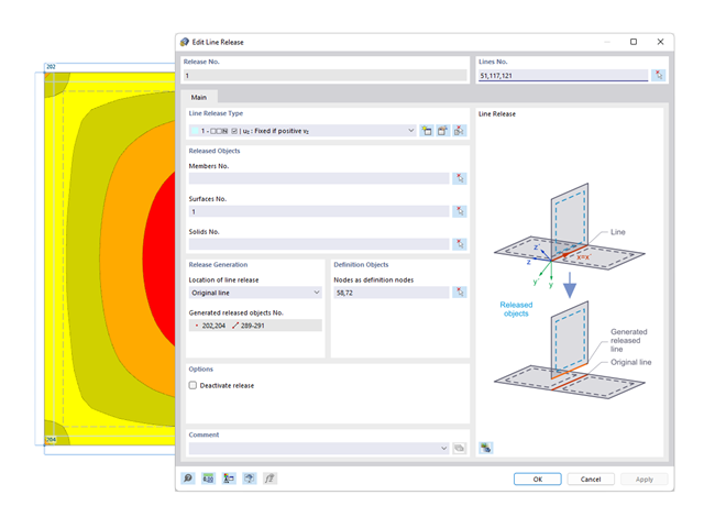
You probably already know that node, line, and surface releases are used to define transfer conditions between objects. For example, you can release members, surfaces, and solids from a line. It is also easily possible for the releases to have nonlinear properties, such as "Fixed if positive n", "Fixed if negative n", and so on.
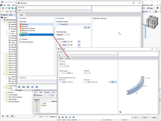
Use the Edit Nodes function to adjust the node type with the automatic specification of all necessary secondary properties. You also have the option to transfer a node to a line or to a member, or to place it between two nodes and two points.

RFEM allows you to use a special line hinge to model the special properties of the connection between the reinforced concrete slab and masonry wall. This limits the transferable forces of the connection depending on the specified geometry. You guess right: This means that the material cannot be overloaded.
The program develops interaction diagrams that are applied automatically. They represent the various geometric situations and you can use them to determine the correct stiffness.
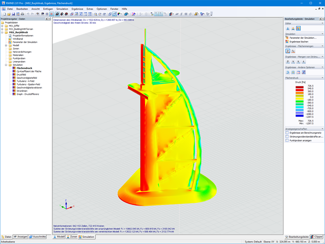
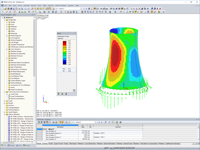
When starting the analysis in the RFEM or RSTAB application, you trigger a batch process. It places all member, surface, and solid definitions of the model rotated with all relevant coefficients in the numerical wind tunnel of RWIND Basic. Furthermore, it starts the CFD analysis, and returns the resulting surface pressures for a selected time step as FE mesh nodal loads or member loads into the respective load cases of RFEM or RSTAB.
These load cases which contain RWIND Basic loads can then be calculated. Moreover, you can combine them with other loads in load and result combinations.
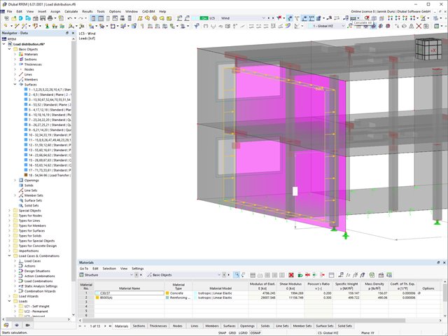
Keep an eye on all surfaces. A surface with the "Load Transfer" stiffness type has no structural effect. You can use it to consider the loads from surfaces that have not been modeled, for example, facade structures, glass surfaces, trapezoidal roof sections, and so on.
Go to Explanatory Video
The form-finding process gives you a structural model with active forces in the "prestress load case" This load case shows the displacement from the initial input position to the form-found geometry in the deformation results. In the force or stress-based results (member and surface internal forces, solid stresses, gas pressures, and so on), it clarifies the state for maintaining the found form. For the analysis of the shape geometry, the program offers you a two-dimensional contour line plot with the output of the absolute height and an inclination plot for the visualization of the slope situation.
Now, a further calculation and structural analysis of the entire model is performed. For this purpose, the program transfers the form-found geometry including the element-wise strains into a universally applicable initial state. You can now use it in the load cases and load combinations.

You can display all essential results on the FE model. In this case, you can filter the results separately according to the respective components.
Furthemore, RFEM delivers you all design checks in a tabular form, including the display of the formulas used. If you wish, you can transfer the result tables to the RFEM printout report.

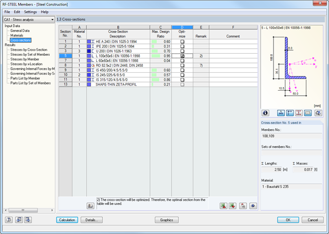
- Cross-section optimization
- Transfer of optimized sections to RFEM/RSTAB
- Design of any thin-walled section from RSECTION
- Representation of a stress diagram on a section
- Determination of normal, shear, and equivalent stresses
- Output of stress components for the individual member internal force types
- Detailed representation of stresses in all stress points
- Determination of the largest Δσ for each stress point (for example, for fatigue design)
- Colored display of stresses and design ratios for a quick overview of the critical or oversized zones
- Output of parts lists

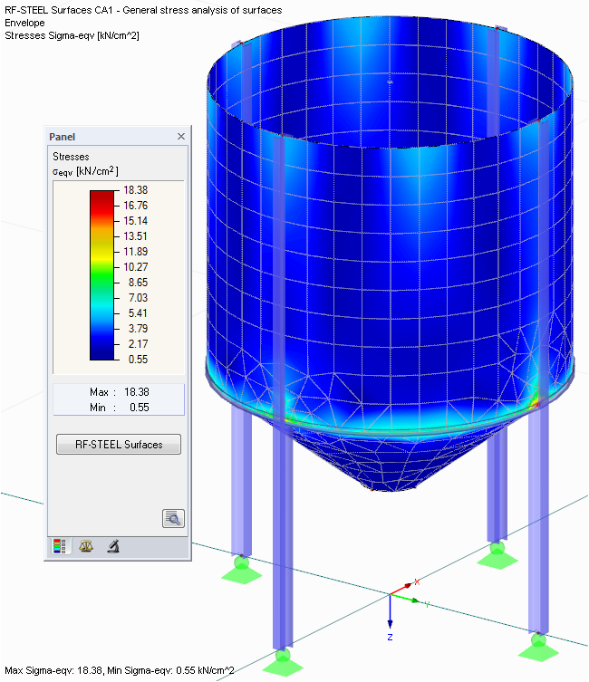
- Determination of principal and basic stresses, membrane and shear stresses, as well as equivalent stresses and equivalent membrane stresses
- Stress analysis for structural surfaces including simple or complex shapes
- Equivalent stresses calculated according to different approaches:
- Shape modification hypothesis (von Mises)
- Shear stress hypothesis (Tresca)
- Normal stress hypothesis (Rankine)
- Principal strain hypothesis (Bach)
- Optional optimization of surface thicknesses and data transfer to RFEM
- Output of strains
- Detailed results of individual stress components and ratios in tables and graphics
- Filter function for solids, surfaces, lines, and nodes in tables
- Transversal shear stresses according to Mindlin, Kirchhoff, or user-defined specifications
- Stress evaluation for welds at connection lines between surfaces (see the Product Feature)
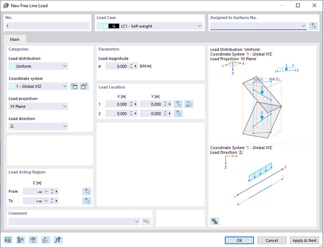
Also for pure member models, such as girder grillages, there is a useful feature for you. Here you can define free line loads (for example, from conveyor belts) and transfer them proportionally to members.
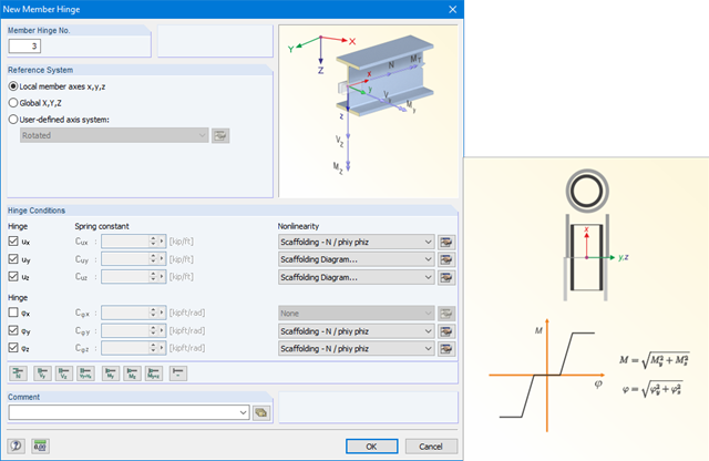
The member hinge nonlinearities "Scaffolding - N phiy / phiz" and "Scaffolding Diagram" enable the mechanical simulation of a tube joint with an inner stub between two member elements.
The equivalent model transfers the bending moment via the overpressed outer pipe and after positive locking additionally via the inner stub, depending on the compression state at the member end.
.png?mw=640&hash=c1087880acc023575381bb136280b0c348568350)
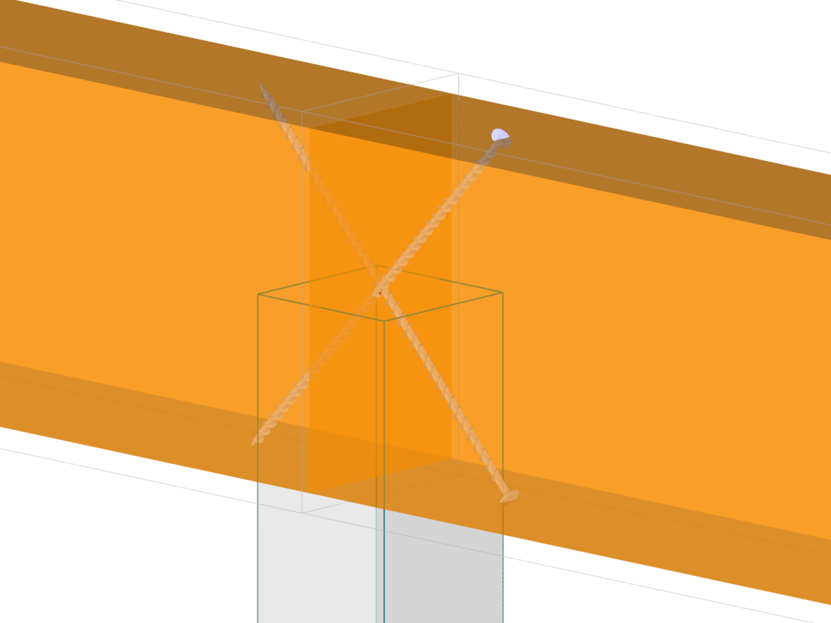
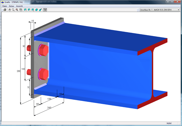
- Design of hinged connections
- Biaxial inclination of the connected member (for example, a jack rafter joint)
- Connection of any number of members on one node for the type "Main member only"
- Screw diameter 6 mm – 12 mm
- Automatic check of the minimum distance between screws
- Optional free definition of screw distances
- Transfer of eccentricity from RFEM/RSTAB
- Crosswise or parallel screw alignment
- Definition of up to 16 screws in a row
- Graphical visualization of joints in the add-on module and in RFEM/RSTAB
- Performing all required designs
- Cross-section optimization
- Transfer of optimized sections to RFEM/RSTAB
- Design of any thin-walled cross-section from SHAPE-THIN
- Representation of a stress diagram on a section
- Determination of normal, shear, and equivalent stresses
- Stress results of individual internal forces types
- Detailed representation of stresses in all stress points
- Determination of the largest Δσ for each stress point (for example, for fatigue design)
- Colored display of stresses and design ratios for a quick overview of the critical or oversized zones
- Parts lists and quantity surveying
- Determination of principal and basic stresses, membrane and shear stresses, as well as equivalent stresses and equivalent membrane stresses
- Stress analysis for structural surfaces including simple or complex shapes
- Equivalent stresses calculated according to different approaches:
- Shape modification hypothesis (von Mises)
- Shear stress hypothesis (Tresca)
- Normal stress hypothesis (Rankine)
- Principal strain hypothesis (Bach)
- Optional optimization of surface thicknesses and data transfer to RFEM
- Serviceability limit state design by checking surface displacements
- Detailed results of individual stress components and ratios in tables and graphics
- Filter function for surfaces, lines, and nodes in tables
- Transversal shear stresses according to Mindlin, Kirchhoff, or user-defined specifications
- Parts list of designed surfaces

- Import of materials, cross-sections, and internal forces from RFEM/RSTAB
- Steel design of thin‑walled cross‑sections according to EN 1993‑1‑1:2005 and EN 1993‑1‑5:2006
- Automatic classification of cross-sections according to EN 1993-1-1:2005 + AC:2009, Cl. 5.5.2, and EN 1993-1-5:2006, Cl. 4.4 (cross-section class 4), with optional determination of effective widths according to Annex E for stresses under fy
- Integration of parameters for the following National Annexes:
-
 DIN EN 1993-1-1/NA:2015-08 (Germany)
 -
 ÖNORM B 1993-1-1:2007-02 (Austria)
 -
 NBN EN 1993-1-1/ANB:2010-12 (Belgium)
 -
 BDS EN 1993-1-1/NA:2008 (Bulgaria)
 -
 DS/EN 1993-1-1 DK NA:2015 (Denmark)
 -
 SFS EN 1993-1-1/NA:2005 (Finland)
 -
 NF EN 1993-1-1/NA:2007-05 (France)
 -
 ELOT EN 1993-1-1 (Greece)
 -
 UNI EN 1993-1-1/NA:2008 (Italy)
 -
 LST EN 1993-1-1/NA:2009-04 (Lithuania)
 -
 UNI EN 1993-1-1/NA:2011-02 (Italy)
 -
 MS EN 1993-1-1/NA:2010 (Malaysia)
 -
 NEN EN 1993-1-1/NA:2011-12 (Netherlands)
 - NS EN 1993-1-1/NA:2008-02 (Norway)
-
 PN EN 1993-1-1/NA:2006-06 (Poland)
 -
 NP EN 1993-1-1/NA:2010-03 (Portugal)
 -
 SR EN 1993-1-1/NB:2008-04 (Romania)
 -
 SS EN 1993-1-1/NA:2011-04 (Sweden)
 -
 SS EN 1993-1-1/NA:2010 (Singapore)
 -
 STN EN 1993-1-1/NA:2007-12 (Slovakia)
 -
 SIST EN 1993-1-1/A101:2006-03 (Slovenia)
 -
 UNE EN 1993-1-1/NA:2013-02 (Spain)
 -
 CSN EN 1993-1-1/NA:2007-05 (Czech Republic)
 -
 BS EN 1993-1-1/NA:2008-12 (the United Kingdom)
 -
 CYS EN 1993-1-1/NA:2009-03 (Cyprus)
 - In addition to the National Annexes (NA) listed above, you can also define a specific NA, applying user‑defined limit values and parameters.
- Automatic calculation of all required factors for the design value of flexural buckling resistance Nb,Rd
- Automatic determination of the ideal elastic critical moment Mcr for each member or set of members on every x-location according to the Eigenvalue Method or by comparing moment diagrams. You only have to define the lateral intermediate supports.
- Design of tapered members, unsymmetric sections or sets of members according to the General Method as described in EN 1993-1-1, Cl. 6.3.4
- In the case of the General Method according to Cl. 6.3.4, optional application of "European lateral-torsional buckling curve" according to Naumes, Strohmann, Ungermann, Sedlacek (Stahlbau 77 [2008], pp. 748‑761)
- Rotational restraints can be taken into account (trapezoidal sheeting and purlins)
- Optional consideration of shear panels (for example, trapezoidal sheeting and bracing)
- RF-/STEEL Warping Torsion module extension (license required) for stability analysis according to the second-order analysis as stress analysis including consideration of the 7th degree of freedom (warping)
- Module extension RF-/STEEL Plasticity (license required) for plastic analysis of cross‑sections according to Partial Internal Forces Method (PIFM) and Simplex Method for general cross‑sections (in connection with the RF‑/STEEL Warping Torsion module extension, it is possible to perform the plastic design according to the second‑order analysis)
- Module extension RF-/STEEL Cold-Formed Sections (license required) for ultimate and serviceability limit state designs for cold-formed steel members according to the EN 1993-1-3 and EN 1993-1-5 standards
- ULS design: Selection of fundamental or accidental design situations for each load case, load combination, or result combination
- SLS design: Selection of characteristic, frequent, or quasi-permanent design situations for each load case, load combination, or result combination
- Tension analysis with definable net cross-section areas for member start and end
- Weld designs of welded cross-sections
- Optional calculation of warp spring for nodal support on sets of members
- Graphic of design ratios on cross-section and in RFEM/RSTAB model
- Determination of governing internal forces
- Filter options for graphical results in RFEM/RSTAB
- Representation of design ratios and cross‑section classes in the rendered view
- Color scales in result windows
- Automatic cross-section optimization
- Transfer of optimized cross-sections to RFEM/RSTAB
- Parts lists and quantity surveying
- Direct data export to MS Excel
- Verifiable printout report
- Possibility to include the temperature curve in the report
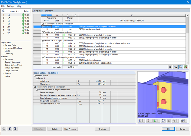
The result windows list all results of the calculation in detail. In addition, 3D graphics are created, where individual components as well as dimension lines and, for example, This allows you, for example, to display or hide the weld data. The summary shows if the individual designs have been fulfilled: The design ratio is additionally visualized with a green data bar, which turns red when the design is not fulfilled. Furthermore, the node number and the governing LC/CO/RC are displayed.
When selecting a design, the module shows the detailed intermediate results including the actions and the additional internal forces from the connection geometry. There is the option to display the results by load case and by node. The connections are represented in a realistic 3D rendering possible to scale. In addition to the main views, it is possible to show the graphics from any perspective.
You can add the graphics with dimensions and labels to the RFEM/RSTAB printout or export them as DXF. The printout report includes all input and result data prepared for test engineers. It is possible to export all tables to MS Excel or in a CSV file. A special transfer menu defines all specifications required for the export.
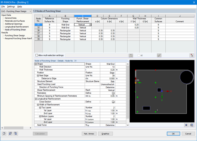
After opening the module, the materials and surface thicknesses defined in RFEM are preset. The nodes to be designed are automatically recognized but can also be modified by the user.
It is possible to consider openings in the area with risk of punching shear. The openings can be transferred from RFEM or specified only in RF‑PUNCH Pro so they do not effect the stiffnesses of the RFEM model.
The parameters of the longitudinal reinforcement are the number and direction of the layers and the concrete cover, specified separately for the top and bottom of the slab on a surface-by-surface basis.
The next input window allows you to define all additional details for nodes of punching shear.
The module recognizes the position of the punching node and automatically sets, whether the node is located in the center of the slab, on the slab edge or in the slab corner.
In addition, it is possible to set punching load, load increment factor β, and the existing longitudinal reinforcement. Optionally, the minimum moments can be activated for determining the required longitudinal reinforcement and enlarged column head.
To facilitate orientation, a slab is always displayed with the corresponding node of punching shear. You can also open the design program by HALFEN, a German producer of shear rails. All RFEM data can be imported to this program for further easy and effective processing.

SHAPE-THIN includes an extensive library of rolled and parameterized cross-sections. They can be composed or supplemented by new elements. It is possible to model a section consisting of different materials.
Graphical tools and functions allow for modeling complex section shapes in the usual way common for CAD programs. The graphical entry provides the option of setting point elements, fillet welds, arcs, parameterized rectangular and circular sections, ellipses, elliptical arcs, parabolas, hyperbolas, spline, and NURBS. Alternatively, it is possible to import a DXF file that is used as the basis for further modeling. You can also use guidelines for modeling.
Furthermore, parameterized input allows you to enter model and load data in a specific way so they depend on certain variables.
Elements can be divided or attached to other objects graphically. SHAPE-THIN automatically divides the elements and provides for an uninterrupted shear flow by introducing dummy elements. In the case of dummy elements, you can define a specific thickness to control the shear transfer.
All design results and design checks are displayed in detail and in a comprehensible manner. An error log indicates non-designable situations or failed recommendations. Due to the permanent integration in RFEM/RSTAB, subsequent modifications in the structural system and in loading are automatically taken into account for the connections to be checked.
If one of the designs could not be fulfilled, the corresponding line is highlighted in red. The output appears in a short or a long form in the global printout report of RFEM/RSTAB. Furthermore, you can easily export all result tables to MS Excel or in a CSV file. A special transfer menu defines all specifications required for the export.
- Full integration in RFEM/RSTAB including import of all relevant information and internal forces
- Design of members and continuous members for tension, compression, bending, shear, and combined internal forces
- Stability analysis for lateral-torsional buckling and buckling according to the equivalent member method or the second order analysis
- Serviceability limit state design by limitation of deflections
- Free configuration of charring time and charring rates, as well as free choice of charring sides for fire design
- South African material library and cross‑section library
- User-defined entry of rectangular and circular cross-sections
- Cross-section optimization with optional transfer to RFEM/RSTAB
- Optional import of effective lengths from the RSBUCK or RF‑STABILITY add‑on module
- Detailed result documentation including references to design equations of the used standard
- Various filter and sorting options of results including result lists by member, cross-sections, x-location, or by load case, load and result combination
- Consideration of moisture service conditions
- Visualization of the design criterion on the RFEM/RSTAB model
- Data export to MS Excel
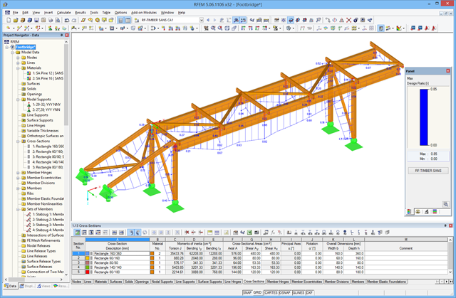
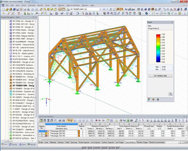
After the calculation, the module displays results in clearly arranged result tables. All intermediate values (for example, governing internal forces, adjustment factors, and so on) can be included in order to make the design more transparent. The results are listed by load case, cross-section, member, and set of members.
If the analysis fails, the relevant cross-sections can be modified in an optimization process. It is also possible to transfer the optimized cross-sections to RFEM/RSTAB to perform a new calculation.
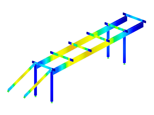
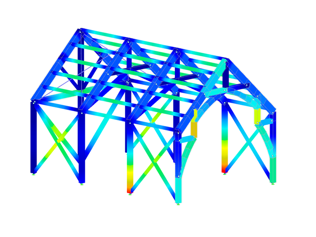
The design ratio is represented with different colors in the RFEM/RSTAB model. This way, you can quickly recognize critical or oversized areas of the cross-section. Furthermore, result diagrams displayed on the member or set of members ensure targeted evaluation.
In addition to the input and result data, including design details displayed in tables, you can add all graphics into the printout report. This way, comprehensible and clearly arranged documentation is guaranteed. You can select the report contents and extent specifically for the individual designs.
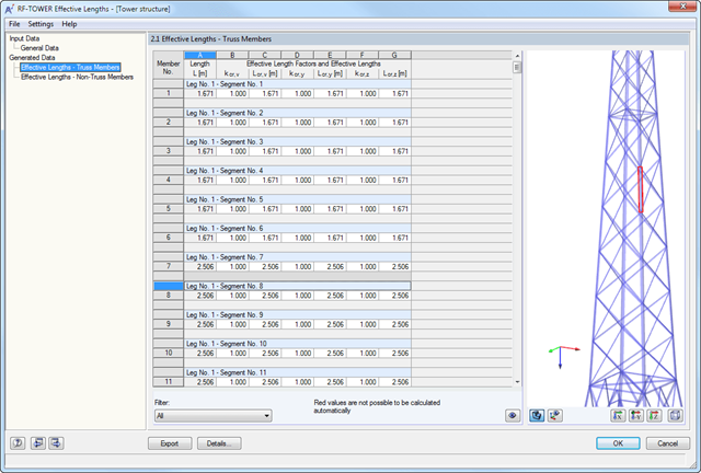
After generating the effective lengths, the results are displayed in clearly arranged tables. You can modify the effective lengths manually there.
The Export function transfers the effective lengths to the RF-/TOWER Design add-on module for further calculation. The complete module data are part of the RFEM/RSTAB printout report. The report contents and the extent of the results can be selected specifically for the individual designs.
After the calculation, the module displays results in clearly arranged result tables. All intermediate values (for example, governing internal forces, adjustment factors, and so on) can be included in order to make the design more transparent. The results are sorted by load case, cross-section, set of members, and members.
If the analysis fails, the affected cross-sections can be modified in an optimization process. It is also possible to transfer the optimized cross-sections to RFEM/RSTAB for a new calculation.
The design ratio is represented with different colors in the RFEM/RSTAB model. This way, you can quickly recognize critical or oversized areas of the cross-section. Furthermore, result diagrams displayed on the member or set of members ensure targeted evaluation.
In addition to the input and result data, including design details displayed in tables, you can add all graphics into the printout report. This way, comprehensible and clearly arranged documentation is guaranteed. You can select the report contents and extent specifically for the individual designs.
- Full integration in RFEM/RSTAB including import of all relevant information and internal forces
- Design of members and continuous members for tension, compression, bending, shear, and combined internal forces
- Stability analysis for lateral-torsional buckling and buckling according to the equivalent member method or the second order analysis
- Serviceability limit state design by limitation of deflections
- Brazilian material library and cross-section library
- User-defined entry of rectangular and circular cross-sections
- Cross-section optimization with optional transfer to RFEM/RSTAB
- Optional import of effective lengths from the RSBUCK or RF‑STABILITY add‑on module
- Detailed result documentation including references to design equations of the used standard
- Various filter and sorting options of results including result lists by member, cross-sections, x-location, or by load case, load and result combination
- Consideration of moisture service conditions
- Visualization of the design criterion on the RFEM/RSTAB model
- Data export to MS Excel